Practical guide
Thermal Bridging vs Air Leakage: Facade Basics
A thermal bridge transfers heat through or around the insulation; air leakage needs a pressure difference and a connected path. They can occur together, and improving one does not establish the other’s performance. Two original mechanism sketches, evidence comparisons, eight explained cases and a downloadable record help you read the actual junction and ask a focused question.
Heat through a solid is different from air through a path
A thermal bridge is a part of an assembly where heat flows more readily than through the surrounding thermal-control arrangement. The path can pass through or around the insulation, and its geometry matters as well as the materials. A conductive frame, connection or floor-edge arrangement can create such a path.
Air leakage is air moving through a connected route under a pressure difference. John Straube’s airflow digest names both prerequisites: a pressure difference and a continuous path connecting the points. For enclosure leakage, the route crosses the building’s air-control boundary.
| Question | Thermal bridging | Air leakage |
|---|---|---|
| Mechanism | A locally easier heat-flow path through or around the thermal insulation. | Air travels through a connected path under a pressure difference. |
| What drives the illustrated flow | A temperature difference; the example concerns conduction through a solid. | A pressure difference, which can come from wind, buoyancy or mechanical systems. |
| Does air have to cross the enclosure? | No. A conductive connection can transfer heat while its air-control junction stays sealed. | Yes, for the enclosure-leakage case discussed here: the path connects across the enclosure. |
| Continuity to inspect | Insulation, conductive crossings and the geometry of the whole junction. | The air-control system, including joints, penetrations and connections. |
| What the other improvement leaves open | Reducing a conductive bridge does not establish airtightness. | Reducing leakage does not remove an unchanged conductive bridge. |
The processes can coexist at the same junction. A metal connection may conduct heat, while an incompletely connected seal around it also permits air movement. Conversely, an airtight junction can still be a thermal bridge. Use two questions rather than choosing one label from the appearance of the facade.
Read two mechanism sketches with different driving conditions
These original diagrams separate the mechanisms. Jump to the heat-path sketch or jump to the air-path sketch. The symbols explain a principle; they do not specify a wall system, connection or installation detail.
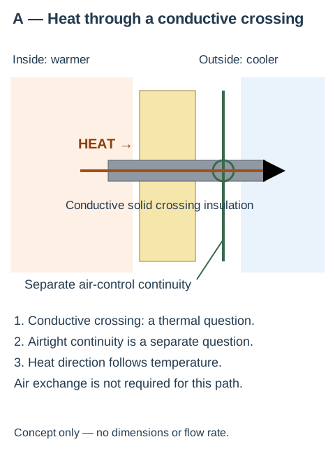
Read A from the warmer side toward the cooler side. The gray solid crosses the yellow insulation field, so the heat-flow question includes the crossing rather than only the insulation product. The continuous green line represents an airtight connection as an assumption of this teaching example. It is not a sealant profile or proof that an installed junction is airtight.
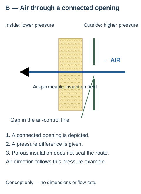
Read B from the higher-pressure side toward the lower-pressure side. The example pressure direction is stated, not inferred from indoor or outdoor temperature. Actual direction can change with wind, buoyancy and mechanical systems. This sketch omits a solid thermal crossing, but it does not claim that all other heat transfer is zero.
Trace thermal continuity and air-control continuity separately
For the thermal question, locate the insulation and any paths that cross or bypass it. At a slab edge, support or frame, follow the actual geometry. A thermal bridge is not defined only by the presence of a particular metal: corners and intersections can create more complex heat flow too. The relevant assessment concerns the complete junction.
For the air-flow question, locate the specified air-control system. Straube emphasizes “system” because a material alone does not provide the whole plane of airtightness. Joints, seams, penetrations, corners and connections all contribute. A line drawn on a broad section needs a continuation through the opening or adjacent detail.
Insulation and an air barrier can be separate layers. Some specified products can have both functions, but that does not make every insulation product an air barrier. Diagram B intentionally uses an air-permeable insulation field to show why a thermal layer need not seal an opening.
Record intended functions before making a performance judgment. “The air-control line is shown continuous at this junction” describes a drawing. “The installed junction is airtight” requires appropriate evidence about the installation. Likewise, “insulation is shown” does not establish that a conductive crossing is adequately addressed.
Use cold spots and visible openings as questions to investigate
A cold interior region can suggest a useful place to look, but it does not identify the whole mechanism. The thermal-control digest discusses cold spots associated with thermal bridges. The testing digest discusses additional investigation, including infrared cameras used by experienced consultants during leakage diagnostics. Neither makes a single unexplained pattern a complete diagnosis.
Keep the location and conditions with an observation. Which facade zone, floor edge, frame or opening was examined? What weather and mechanical-system conditions were recorded? Does the image match a known detail, and was further investigation carried out? A cropped image can omit the information needed to interpret it.
A visible joint is also not a complete route. It may lead into an exterior cavity, stop at another air-control layer or connect through an interface hidden from this view. Trace the intended boundary and the adjoining details before labeling it enclosure leakage.
Separate air movement outside the air-control boundary from leakage into the conditioned space. A rainscreen cavity can have intentional ventilation and drainage. The rainscreen and curtain-wall comparison explains those different roles. The useful question is where the path goes, rather than whether every part of a facade contains moving air.
Read the scope of drawings, thermal work and airtightness tests
An airtightness test measures airflow together with the pressure difference across the tested enclosure. Its result depends on the boundary, preparation and method. A component test and a whole-building test answer different questions; a material result does not include every field joint made with that material.
Straube’s testing digest explicitly distinguishes the overall leakage result from locating individual leaks. Additional investigation can help find significant paths, but the total airflow alone does not map their positions. It also does not measure heat conducting through solid connections.
| Evidence | What it can support | What remains open | Question to ask |
|---|---|---|---|
| A section or junction detail | Documents intended layers, geometry and connections at its cut. | Does not verify concealed installation or actual performance. | Which drawing and revision continue the thermal and air-control paths? |
| A thermal calculation | Estimates heat flow or surface conditions for a modeled assembly and assumptions. | Does not measure air leakage through the installed enclosure. | What geometry, material inputs and boundary conditions were used? |
| An infrared survey | Can help identify patterns for further investigation; consultants may use it during leakage diagnostics. | A pattern alone does not establish the mechanism or every hidden opening. | What conditions, location and additional investigation support the interpretation? |
| A whole-building airtightness test | Measures airflow and pressure across the enclosure under the stated preparation and method. | The total alone does not locate each leak or measure thermal bridging. | What boundary, openings, pressure/flow data and reporting method are included? |
| A component or local investigation | Describes the tested product, junction or location under its own scope. | Does not establish that every interface or the whole building behaves identically. | Which configuration was examined, and which adjacent connections remain outside the scope? |
When comparing reports, retain the pressure, airflow units, tested boundary, treatment of intentional openings and method of normalization. Different pressures or different size bases can make bare numbers misleading. This guide does not assign a leakage target or tell you how to prepare or run a test.
The references are dated technical explanations from 2007, 2011 and 2014. Their concepts help you read mechanisms and evidence. Actual project methods, acceptance criteria and design requirements belong to the current applicable documents and the people assessing the specified assembly.
Write a question that matches the unresolved mechanism
A focused thermal question might be: “Which assessment includes the floor-edge geometry and this connection crossing the insulation?” It identifies the actual junction instead of asking whether the whole facade is “energy efficient.” Keep the drawing reference and revision beside the question.
A focused air-control question might be: “Which opening detail shows how the air-control layer connects to this frame?” If the route is documented but performance remains uncertain, ask what inspection or testing evidence covers that interface.
For an existing observation, state the limit: “A colder area was reported at this floor edge; the cause is not established by the image alone.” Then identify the matching assembly information and further evidence needed. This makes the note useful without declaring a hidden defect or an approved repair.
Keep other enclosure functions visible. A thermal or air-control question does not replace the structural role of a support or the rain-management role of a cavity. For those distinct tasks, use the slab and load-path comparison and the water-path section guide. Coordinated details can answer several questions while keeping their evidence separate.
Practice eight mechanism and evidence decisions
These fictional cases contain only the conditions stated. Decide what they support, name what remains unknown, then open the explanation. They are reading exercises rather than inspected buildings, test results or construction instructions.
Case 1
A conductive metal connection crosses the insulation. Its air-control junction is described as sealed. Must air leak through it for a thermal bridge to exist?
Show answer and explanation for case 1
No. Heat can conduct through the solid connection while the air-control junction remains sealed.
The mechanisms have different prerequisites. A temperature difference can drive heat through a conductive solid; enclosure air leakage needs a pressure difference and a connected air path. The fictional description supports a possible thermal bridge without establishing leakage. Actual thermal significance and airtightness still need the assembly’s own evidence.
Case 2
A gap is drawn in the air-control layer, but the sketch does not show whether it connects all the way to the occupied space. Has an enclosure leakage route been established?
Show answer and explanation for case 2
Not yet. Trace the connected path and identify the relevant pressure difference.
An isolated gap is a clue to investigate, not a complete flow route. It may connect into another layer or an exterior cavity. Find the adjoining details and the intended air-control boundary. Airflow needs both connected points and a pressure difference; do not extend a blue arrow through unknown construction to finish the sketch.
Case 3
Two spaces have different temperatures. No connected opening between them is shown. Does that temperature difference alone prove air leakage?
Show answer and explanation for case 3
No. It can drive heat transfer without providing an air-flow path.
Temperature differences and buoyancy can contribute to pressure conditions, but an air-flow connection is still required. Heat may conduct through materials or transfer by other mechanisms without air crossing the enclosure. Keep the heat-flow question separate from the existence and continuity of a leakage route.
Case 4
A survey shows a colder region near a floor edge. Can that pattern alone distinguish a conductive bridge from air leakage?
Show answer and explanation for case 4
No. Treat the pattern as evidence needing context and further investigation.
A cold region can guide a question about thermal geometry, air movement or other conditions. The image alone does not supply the whole assembly or a pressure/flow measurement. Review the matching detail and survey conditions. Where leakage is suspected, appropriate localized investigation and testing can supply additional evidence.
Case 5
In a fictional comparison under matching test conditions, sealing a joint reduces measured airflow. A metal connection crossing the insulation is unchanged. Is the conductive path necessarily removed?
Show answer and explanation for case 5
No. The leakage improvement does not remove an unchanged solid thermal path.
The stated test result concerns air flow. A conductive crossing can remain even after its surrounding joint becomes tighter. Evaluate the thermal geometry separately rather than converting an airflow result into a thermal rating. The comparison is an invented learning case, not a report of tested construction or a promise of energy savings.
Case 6
A whole-building airtightness report meets its stated project target. Does that result prove there are no thermal bridges at the facade?
Show answer and explanation for case 6
No. An airtightness result is not a thermal-bridge assessment.
The test quantifies air leakage within its boundary and conditions. Thermal bridges concern heat-flow paths through materials and geometry. A building can have low measured leakage while conductive crossings remain. Read the thermal assessment and relevant interface details separately, keeping each result within its own scope.
Case 7
An insulation product has a declared thermal resistance. Is that label enough to establish the airtightness of a wall assembled with it?
Show answer and explanation for case 7
No. Check the actual air-control system and its connections.
A product’s thermal property does not describe every joint, penetration or adjacent layer. Some specified materials can perform more than one function, but the complete system still needs continuity and suitable evidence. Do not assign air-control performance from the insulation label alone or generalize one product’s properties to all insulation.
Case 8
A rainscreen cavity is intentionally ventilated outside a documented air-control boundary. Is air movement in that cavity automatically leakage into the occupied building?
Show answer and explanation for case 8
No. Locate the flow relative to the occupied-space air-control boundary.
Deliberate exterior-cavity ventilation and uncontrolled enclosure leakage are different routes. Check whether a connected path crosses the air-control system into the conditioned space. The cavity’s drainage and ventilation have their own documented roles. A drawing-reading exercise should identify those roles rather than treating every visible opening as an instruction to seal it.
Use a two-path record for the next facade question
Download the thermal-bridge and air-leakage reading record (TXT). It includes two blank location records, candidate-evidence rows, the comparison tables and all eight explained cases. Keep the record with the drawing or observation it refers to.
Location, drawing or report reference and revision:
Thermal question — insulation and conductive or geometric crossing:
Air-flow question — air-control boundary and connected path:
Stated driving conditions — temperature and pressure kept separate:
What is documented or observed:
What remains a hypothesis:
Evidence needed, including its boundary and conditions:
One focused question and the relevant detail or report:
What the answer changes in the record:
If the answer resolves one mechanism, update that field without silently claiming the other is solved. A leakage improvement can leave a conductive crossing unchanged; a thermal improvement can leave a joint’s air-control continuity unresolved. An effective record makes both questions visible.
Return to the curtain-wall parts and load-path introduction if the enclosure arrangement is unfamiliar. Once you know what the parts do, follow the thermal and air paths at one junction at a time. The useful conclusion names the evidence you have and the specific question that still needs an answer.
Sources and further reading
- John Straube: BSD-011 — Thermal Control in Buildings, 2011Heat-transfer mechanisms, thermal-bridge geometry and conductive bypass, and the separate contribution of air leakage. Numerical performance examples are not generalized to another assembly.
- John Straube: BSD-014 — Air Flow Control in Buildings, 2007Pressure difference plus a connected path, wind/stack/mechanical driving forces, and air-barrier system continuity. Historical material and code prescriptions are not used as current design requirements.
- John Straube: BSD-040 — Airtightness Testing in Large Buildings, 2014Pressure/flow testing, preparation and reporting scope, material/component versus whole-enclosure evidence, and the need for additional investigation to locate leakage. No test target or savings percentage is prescribed here.