Practical guide
How to Read a Facade Section: Water Paths and Drainage Cavities
Start with the cut and its orientation, then follow the documented water-control layers to their next junction or exit. Keep surface shedding separate from drainage behind the cladding. At a window, floor line or base, stop where the route is not shown and find the detail that continues it. This original annotated section and worksheet help you record what the drawing establishes and what still needs clarification.
Establish what this section cuts through
A facade section is a cut through part of a building’s exterior assembly. It can show depth, layer order and a connection that an elevation conceals. It shows the location of that cut; it does not automatically show every opening, corner or lateral termination.
Read the section marker and drawing reference first. Is this a broad wall section, a enlarged opening detail, a product sketch or a concept diagram? Find its position in the elevation or plan. A drawing through the middle of a window is different from one through its jamb, even if both belong to the same facade.
Mark outside and inside from the drawing. Then identify the exact system or wall type named in the notes. Keep the drawing number and revision with your observations so that a question can be answered against the same information.
The task here is reading a documented route, rather than choosing a wall system or approving a detail. The rainscreen and curtain-wall comparison addresses the separate question of what those classifications describe.
Identify layer functions before following the lines
In a drained wall, an outer cladding screens the assembly, while a connected drainage space and water-control plane deal with water that passes that outer surface. John Straube’s rain-control digest describes that strategy alongside storage and exclusion approaches. Do not assume every wall uses the same arrangement.
Joseph Lstiburek’s drainage-plane digest explains that a water-repellent layer behind the cladding connects with flashings, openings and penetrations to direct water down and out. The layer may be a membrane, sheathing arrangement or another specified system; its identity should come from the documents.
Read the labels by function. A drainage plane is often called a water-resistive barrier, or WRB. One layer may also perform air-control or vapor-control functions, but “air barrier” alone is not proof of rainwater control in every assembly. Write the specified roles separately, even when the same material has more than one job.
Locate the drainage space as well as the plane. A wide-looking cavity with no identified water-control surface does not resolve the whole route. Conversely, a line drawn as a membrane does not show that its connections to the next layer are complete.
Read two annotated sections without filling the gaps by guesswork
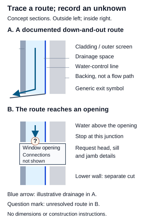
In A, start at the outer screen on the left. The blue area represents a drainage space, the thin blue line a documented water-control plane, and the gray backing sits farther inside. Follow the blue arrow down the space and toward the generic exit symbol. The arrow explains a possible gravity-drainage route; it does not specify a flashing profile.
In B, water above the opening reaches a junction marked with a question mark. The upper and lower wall portions are shown separately. The drawing does not tell you how the opening connects them, so the next step is to find the opening details. Do not extend the arrow through the window or invent an outlet merely to make the drawing look complete.
The question mark is an information limit, not a diagnosis of a leak. A relevant connection may be documented on another sheet. Keep “not shown in this cut” separate from “not provided in the assembly.”
Neither sketch includes support design, dimensions, material selection, seals, fire-related details or installation instructions. Actual systems have those requirements; the learning drawing cannot supply them.
Keep surface shedding separate from water behind the cladding
First read what happens on the outside face: projections, roof edges, canopies and opening geometry may direct surface water. Then ask what happens to water that reaches behind the outer screen. These are connected rain-control questions, but they are different routes on the section.
Gravity drainage is not pressurized flow through a pipe. Straube describes water flowing down while clinging to a surface in the drainage space. Locate the relevant surface and its continuation instead of drawing a thick arrow through the middle of every material.
At a base or interruption, follow the documented transition toward an outlet or another receiving drainage space. Lstiburek notes that an opening may drain into the space behind cladding where that is the intended arrangement. “Outward” therefore does not mean that every component must discharge immediately through the exterior face at its own level; the eventual route still needs to be documented.
Drainage and drying also differ. A traced outlet does not establish every drying mechanism or the wall’s moisture performance. Likewise, an empty gap on a section is not by itself evidence of an effective ventilation or pressure-response arrangement. Keep those separate questions with the specified system information.
Use an eight-step reading sequence
| Step | What to identify | Next check |
|---|---|---|
| 1. Establish the cut | Read the drawing number, section marker, scale, orientation and system name. | Find the matching elevation or plan; know which location the cut represents. |
| 2. Mark outside and inside | Identify the exterior face, backing and occupied side from the drawing. | Do not let a familiar page layout decide the orientation. |
| 3. Name the documented layers | Locate cladding, drainage space, water-control plane and other labeled functions. | Check the legend, specification and product detail when a line has no clear role. |
| 4. Follow surface shedding | Read where rain on the outer face is directed at projections and openings. | Keep this route separate from water behind the cladding. |
| 5. Trace water behind the screen | Follow the documented drainage surface and connected space toward the next exit or junction. | Stop where the route is not shown; record the next detail needed. |
| 6. Examine the interruption | At a window, floor line, balcony or base, identify the detail callout and receiving layer. | Do not draw an imaginary connection through an unknown joint. |
| 7. Check another view | Use head, sill, jamb, corner, plan or three-dimensional details as appropriate. | A vertical cut cannot show every lateral termination or end condition. |
| 8. Record the limit | Separate observed lines, stated system functions and unresolved continuity. | Write a focused question instead of declaring the assembly waterproof. |
Use the sequence on one location at a time. A wall base, a balcony connection and a window opening may have different routes and detail references. Keep each observation attached to its own drawing location rather than transferring one path to the whole elevation.
An annotation can be simple: mark the outside face, number the documented layers, trace the intended drainage direction and circle the first unresolved junction. Add the detail number you need beside the circle. That makes the note useful to another reader without presenting an assumed connection as a fact.
At openings and transitions, ask for the view that resolves the connection
A window interrupts the wall’s layer sequence. Look separately at the wall above the opening, the head, sill and jambs, and the window component. The wall drainage plane, the drained opening and drainage within a window frame are related scales; one small frame detail does not explain all three.
A central vertical sill cut cannot show every lateral end condition. Follow the references to the jamb, plan, corner or three-dimensional detail where necessary. Record the intended receiving layer and outlet without assuming how the ends are closed or connected.
Use the same approach at floor lines, parapets, balcony attachments and changes between facade systems. Ask which drawing connects the adjoining zones and which product or project documents define that interface.
A support rail or cavity barrier can interrupt the visible space on a sketch. Identify its role and coordinated detail rather than treating it as a disposable obstruction to your arrow. Reading the route does not authorize changing structural support or a fire-related component.
When the answer remains unclear, a precise question helps: “Which detail shows how the drainage plane above this opening connects to the head and outlet?” That is more useful than a broad claim that the facade looks waterproof or badly designed.
Record what the drawing establishes and what it cannot verify
| Subject | Question about this section | Evidence to request |
|---|---|---|
| Water-control line | Which specified material or system performs rainwater control here? | Does its identity and connection continue into the adjacent detail? |
| Drainage route | Where does water on the relevant surface go next? | Is the next outlet or receiving drainage space documented? |
| Opening | How are the opening, head, sill and jamb integrated with the wall? | Which cut or system drawing shows the connections that this section omits? |
| Support or barrier | What role does the rail, connection or cavity barrier have? | How does the specified assembly coordinate its function with drainage? |
| Transition | Are the adjoining zones the same system or different systems? | Who or what document defines their interface? |
| Evidence | Is this a concept sketch, project detail, product detail or observed installed condition? | What additional evidence is needed before a performance conclusion? |
A concept diagram explains a principle. A project detail documents an intended assembly. A manufacturer detail describes a particular system or configuration. An inspection or test reports an observed condition under its stated scope. Keep those evidence types distinct.
Tracing a complete route on paper cannot verify concealed installation, material compatibility, seal continuity, tolerances or actual water performance. If a performance conclusion is needed, it requires the appropriate project evidence and assessment.
The source digests are dated technical explanations: 2011 for rain control and 2006 for drainage planes. This guide uses their layer and continuity concepts. It does not adopt their numeric gap dimensions, material prescriptions, climate recommendations or historical examples as current project requirements.
Practice six reading and evidence decisions
These original fictional situations test how you handle a visible line, a missing view and an intended water path. They are not reports of inspected buildings.
Case 1
A vertical wall section shows a drainage gap reaching the top of a window, but no continuation detail. Does the drawing prove either that water escapes safely or that the assembly leaks?
Show answer and explanation for case 1
Neither conclusion follows from that section alone.
The visible route reaches an interface whose treatment is not shown. Mark the point and request the referenced head, opening and adjacent wall details. The outlet may be defined elsewhere, or the documents may need clarification; an omitted line in this one cut is not evidence of an installed defect. The useful observation is precise: “The drainage route above the opening reaches this junction; its continuation is unresolved in this drawing.”
Case 2
A section labels one membrane “WRB / air barrier.” Can you infer that every membrane called an air barrier on another project also performs rainwater control?
Show answer and explanation for case 2
No. Read the functions specified for the actual layer and system.
This drawing assigns two functions to one layer. Another assembly may separate those functions or use a different material arrangement. A label is a starting point for reading the specification and transitions, not permission to apply one project’s meaning to another. Keep water control, air control and vapor control in separate notes even when a product performs more than one role. The new detail still needs its own documented connections.
Case 3
A central vertical cut through a window sill does not show what happens at either jamb. Is that proof the sill has no lateral termination or end treatment?
Show answer and explanation for case 3
No. Those locations may require a different view or detail.
A cut through the middle of an opening shows the geometry at that cut, rather than both ends of the sill. Look for the jamb detail, plan view, corner detail or an appropriate three-dimensional system drawing. Record which view is missing instead of sketching an assumed end condition. If the documentation does not resolve it, ask a focused question about how the sill drainage connects at the jambs.
Case 4
A support rail or cavity barrier crosses the drawn drainage space. Should a reader enlarge or remove it to create a straighter blue arrow?
Show answer and explanation for case 4
No. Identify its function and the specified coordinated detail.
A schematic water arrow is not authority to modify a support, fire-related component or enclosure system. The crossing element may have a necessary role, and drainage may be coordinated through a detail not visible at this scale. Ask how the documented assembly handles the junction and where to find that information. Do not turn a drawing-reading exercise into an unreviewed installation change.
Case 5
A published product detail shows a drained window opening. Can it be copied into a section for a different wall and window system without checking their interface?
Show answer and explanation for case 5
No. A product example does not establish another assembly’s compatibility.
Check the actual products, substrate, adjacent water-control layer, opening geometry and project details. A manufacturer’s drawing can explain its intended system, but the connection to a different system remains a separate question. Keep the example’s designation and limits with your notes. If the project uses another configuration, ask for the coordinated detail rather than treating similar-looking lines as interchangeable.
Case 6
Your annotated section has a complete blue path to an exterior outlet. Has the annotation verified that the installed facade will pass a water test?
Show answer and explanation for case 6
No. A traced drawing route is not a test or inspection result.
The annotation can explain what the documents appear to intend and identify a place needing further evidence. It cannot verify installed materials, seals, tolerances, concealed interfaces or actual performance. Record whether you reviewed a concept, project document, product drawing or observed condition. Any relevant testing, inspection or design assessment needs its own evidence and scope; do not label a classroom diagram as professional approval.
Use the annotated drawing and question sheet
Download the annotated facade-section SVG and the section-reading and interface question sheet. The sheet includes the eight steps, six question prompts, all explained practice cases and two blank location records.
For each location, record the drawing reference, cut direction, documented layers, route to the next junction and the first missing connection. Separate your observation from the question you want answered. Revise the record when you find the relevant detail.
A useful note might read: “The section shows the wall drainage space reaching the window head. Detail H is referenced; I still need the jamb view to understand the lateral connection.” That is an invented reading example. It states a limit without pretending to approve or condemn a real assembly.
For a separate structural reading, use the floor-slab and enclosure section comparison. For the visible exterior face, return to the facade parts introduction. Keep the question you are answering visible as you move between drawings.
Sources and further reading
- John Straube: BSD-013 — Rain Control in Buildings, 2011Selected text 0:17400: surface deflection, drained-screened wall roles, gravity drainage, openings/interruptions and the distinction between drainage and drying. Numeric dimensions, climate/material prescriptions and performance statistics are not adopted.
- Joseph Lstiburek: BSD-105 — Understanding Drainage Planes, 2006Complete captured text read: water-control plane functions, connections with openings and flashings, downward/outward drainage, multiple layer functions and different scales of enclosure/component drainage. Not current project specifications.